What is a U Tube Heat Exchanger
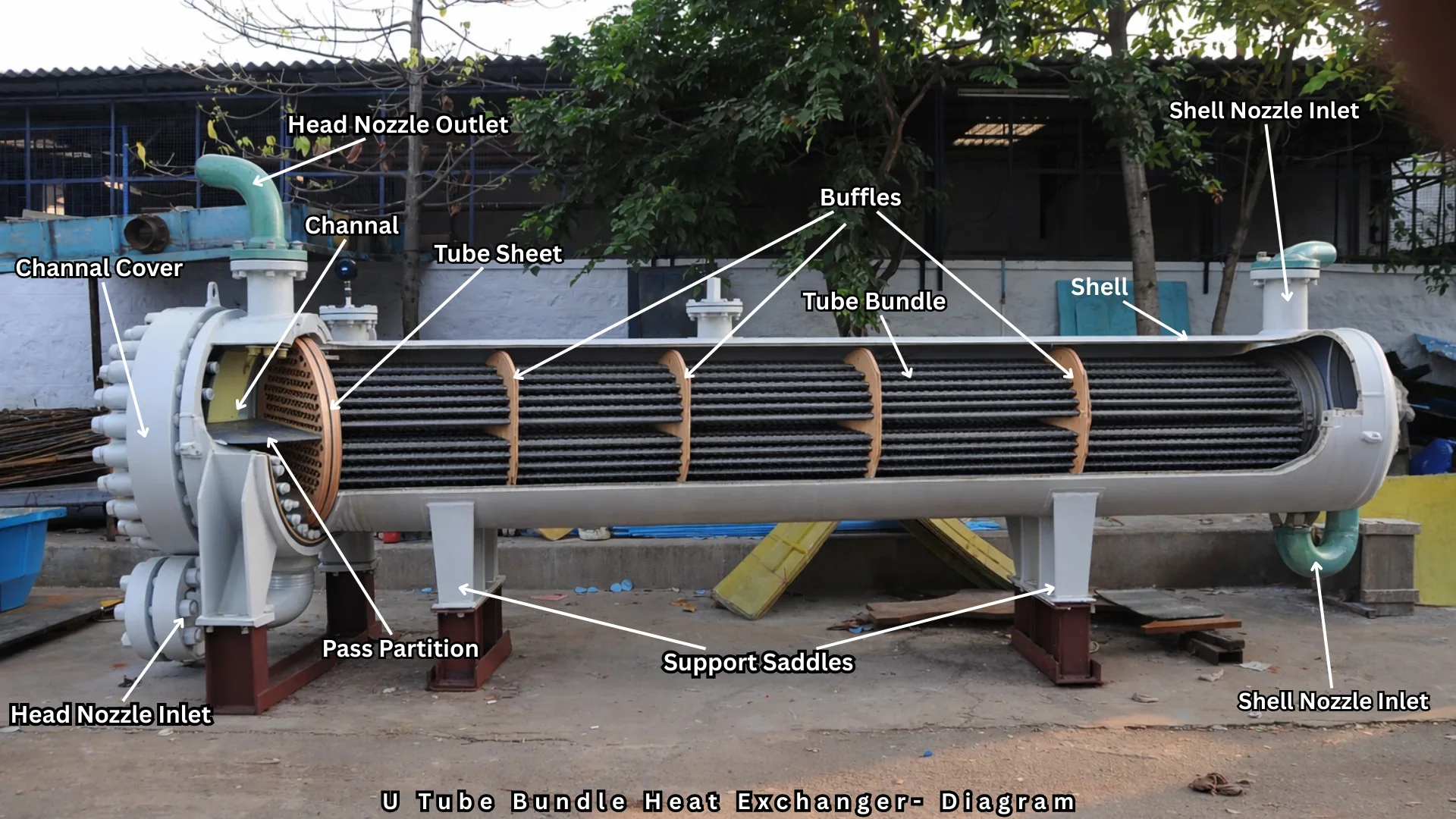 A U-tube heat exchanger is a type of shell-and-tube device where tubes are bent into a U-shape and attached to a single tubesheet. This design lets the tubes expand and contract freely under high temperatures, reducing thermal stress and cutting manufacturing costs.
Key Advantages
- Thermal Expansion: Handles large temperature differences between shell and tube fluids without mechanical stress or expansion joints.
- Cost Effective: Uses only one tubesheet and a removable bundle, making it cheaper than floating-head designs.
- Compact Footprint: Requires less installation space than straight-tube equivalents with equal surface area.
Main Limitations
- Hard to Clean Inside: U-bends prevent mechanical cleaning inside the tubes, so clean tube-side fluids are required.
- Individual Tube Replacement: Replacing inner tubes in the bundle is difficult or impossible without unstacking outer layers.
Common Applications
- Chemical processing and petroleum refining.
- Power plants and steam generators.
- High-pressure and high-temperature reboilers and heaters.
A U-tube heat exchanger is a shell and tube heat exchanger whose tubes are bent into a “U” (hairpin) shape. Both ends of every tube are fixed into a single tubesheet, and the curved end sits free inside the shell.
That one design choice solves a major problem in shell and tube exchangers: differential thermal expansion. In a fixed tubesheet exchanger, the hot tubes and cooler shell expand by different amounts, creating stress. In a U-tube unit, the bundle is anchored at one end only, so the tubes can expand and contract freely.
In one line: a U-tube exchanger is a low-cost, thermally flexible, removable-bundle exchanger best suited to clean tube-side fluids.
2. Working Principle
Heat moves from the hot fluid to the cold fluid through the tube wall by three steps: convection to the wall, conduction through it, and convection away from it.
Step by step:
- The tube-side fluid enters the channel (front head) through the inlet nozzle.
- A pass partition plate sends it into the upper (or one) half of the tubes.
- It flows along the straight length, around the U-bend, and back through the other half of the tubes.
- It leaves through the channel outlet nozzle.
- Meanwhile, the shell-side fluid enters the shell nozzle and flows across and along the tubes, directed by baffles.
- It exits through the shell outlet nozzle.
- Because the tube fluid goes out and returns, the tube side always has an even number of passes (2, 4, 6, and so on).
3. Construction and Components
| Component |
Function |
| U-Tube Bundle |
The heat transfer surface: tubes bent in a U shape |
| Tubesheet |
A single thick plate holding all tube ends, separating shell and tube fluids |
| Shell |
Cylindrical pressure vessel around the bundle |
| Front Head / Channel |
Distributes and collects the tube-side fluid |
| Pass Partition Plate |
Separates inlet and outlet halves of the channel |
| Baffles |
Support tubes, prevent sagging, and direct shell-side flow for better heat transfer |
| Tie Rods and Spacers |
Hold baffles in position |
| Impingement Plate |
Protects tubes from high-velocity inlet flow |
| Nozzles |
Inlet and outlet connections |
| Support Saddles |
Mount the exchanger |
| Sealing Strips / Dummy Tubes |
Block shell-side bypass through the open center of the bundle |
A special feature: the inner U-bends have a very small radius, so a tube-free lane often exists at the center of the bundle. Without sealing strips or dummy tubes, shell-side fluid bypasses the tubes through this lane and efficiency drops.
4. TEMA Designations
TEMA (Tubular Exchanger Manufacturers Association) names a shell and tube exchanger with three letters:
front head, shell type, rear head.
In a U-tube exchanger the rear head letter is “U”, meaning a U-tube bundle.
Common examples:
- BEU: bonnet front head, single-pass shell, U-tube bundle
- AEU: channel with removable cover, single-pass shell, U-tube bundle
- AKU / BKU: U-tube bundle in a kettle-type reboiler (very common in process plants)
- AJU: divided-flow shell type with U-tubes
Related standards:
TEMA Standards, ASME Section VIII Division 1, API 660 / ISO 16812 ASME Section II for materials.
5. Flow Arrangement and Temperature Profile
A U-tube exchanger with a single shell pass and two tube passes is a
1-2 arrangement. Part of the flow is counter-current and part co-current, so it does not achieve pure counterflow.
Heat duty is calculated as:
Q = U × A × F × ΔT_lm
- ΔT_lm is the log mean temperature difference for pure counterflow.
- F is the correction factor (less than 1) that accounts for the mixed flow pattern. Designers typically want F ≥ 0.8 or so. A very low F means a temperature cross problem, and you should consider multiple shells in series.
When a temperature cross occurs (the cold fluid outlet exceeds the hot fluid outlet), a single 1-2 unit loses efficiency quickly. Two shells in series are then the usual fix.
6. Advantages
- Free thermal expansion :LTubes expand independently of the shell, so there is no need for an expansion joint.
- Lower cost than floating head: :Only one tubesheet, with no floating head cover or split ring.
- Fewer leak points :Only one tubesheet joint set must be sealed, which matters for hazardous or high-pressure service.
- Removable bundle:The bundle can be pulled for shell-side inspection and cleaning.
- Handles large temperature differences: between the two fluids.
- High pressure capability: Works well when the tube side is high pressure, since tubes in a single thick tubesheet resist pressure well.
- Reduced weight and fabrication complexity: compared with floating head designs.
7. Disadvantages and Limitations
- Hard to clean the tube side mechanically: Rigid rods cannot pass around the bends, so chemical cleaning or flexible high-pressure lances are used.
- Difficult tube replacement: Typically only outer-row tubes can be pulled. Inner tubes are plugged when they leak.
- Fewer tubes per shell diameter: The tight inner bends and central lane reduce tube count, so the area is lower than in a straight-tube bundle of the same shell size.
- Erosion at U-bends: High velocity or entrained solids cause wear at the bend.
- Wall thinning at bends: The tube outer wall thins during bending, so a thicker tube or a larger bend radius is used.
- Residual stress at bend: Small-radius bends may need stress-relief heat treatment, depending on material and code.
- Even tube-side pass count only.
- Not ideal for fouling tube-side fluids such as slurries, scaling water, or polymerizing products.
- Shell-side bypass through the central lane if sealing is poor.
8. Design Guidelines
Fluid Allocation
| Condition |
Tube Side |
Shell Side |
| Fouling Fluid |
No (hard to clean) |
Yes (bundle is removable) |
| High Pressure |
Yes |
No |
| Corrosive Fluid |
Yes (only tubes and head need expensive alloy) |
No |
| Clean Fluid |
Yes |
Either |
| Low Flow Rate |
Often shell side (baffles create turbulence) |
Yes |
Tube Selection
- Common OD: 19.05 mm (3/4 in) or 25.4 mm (1 in)
- Common wall thickness: 1.65 mm to 2.77 mm, increased at the bend if thinning is a concern
- Minimum bend radius: commonly about 1.5 times the tube OD (centerline) as a practical limit, but follow manufacturer and code limits.
- Straight lengths often between 3 m and 9 m.
Tube Layout
- Triangular pitch (30°): more tubes, higher heat transfer, but not cleanable by lance on the shell side.
- Square pitch (90° or 45°): allows mechanical cleaning lanes on the shell side. Use for fouling shell-side fluids.
Pitch is typically 1.25 to 1.5 times the tube OD.
Velocity Limits (typical guide values)
- Water in tubes: roughly 1 to 2.5 m/s (lower to avoid erosion at bends, higher to reduce fouling)
- Liquids on shell side: about 0.3 to 1 m/s
- Avoid very high velocities at U-bends, especially with two-phase flow or solids.
Baffles
- Segmental baffles with 25% cut are the common default.
- Baffle spacing between 0.2 and 1 shell diameter.
- Keep the unsupported span in the U-bend region within vibration limits. Add support at or near the bend to reduce flow-induced vibration.
Pressure Drop
Typical allowable pressure drops: about
0.5 to 0.7 bar for liquids on the shell side and
0.7 to 1 bar on the tube side, varying by service and economics.
Design Steps
- Define duty, flow rates, temperatures, and pressures.
- Choose the fluid allocation.
- Estimate U from tables.
- Calculate LMTD and the F factor.
- Compute the required area A = Q / (U × F × ΔT_lm).
- Select tube size, length, and layout.
- Calculate the number of tubes and shell diameter.
- Calculate tube-side and shell-side heat transfer coefficients and pressure drops.
- Recalculate U and check the area margin (usually 10 to 20% over the clean requirement).
- Check vibration, mechanical design, and TEMA/ASME compliance.
9. Materials of Construction
| Part |
Common Materials |
| Tubes |
Carbon steel (SA-179, SA-214), stainless steel (304/316), copper-nickel, titanium, duplex stainless, Inconel/Incoloy (high temperature and nuclear) |
| Shell |
Carbon steel (SA-516 Gr. 70), stainless steel, alloy steel |
| Tubesheet |
Carbon steel, with alloy cladding or overlay if corrosive |
| Baffles |
Carbon steel, stainless steel |
| Gaskets |
Spiral wound, metal jacketed, or other |
Selection tips:
Use titanium or copper-nickel for seawater.
Use stainless or duplex for chloride-bearing or corrosive process fluids, taking care with stress corrosion cracking.
For steam service, carbon steel is common.
Check galvanic compatibility between tube and tubesheet metals.
10. Fouling, Cleaning, and Inspection
Fouling Types
Scaling (hard water), particulate, biological, corrosion, and chemical reaction fouling.
Fouling Factors
Designers add
fouling resistances to the calculation, which lowers the effective U. Typical values for water and process fluids are available in TEMA tables.
Cleaning Methods
| Side |
Method |
| Shell Side |
Pull the bundle, then hydro-blast, steam clean, chemical clean, or mechanically clean (square pitch lanes) |
| Tube Side |
Chemical cleaning, flexible lance high-pressure water jetting, and online cleaning systems (e.g., sponge ball or brush systems) in some services |
| Not Possible |
Rigid rodding through the U-bend |
Inspection Techniques
- Eddy current testing (ECT) for tube wall thinning and cracking, including U-bends with specialized probes
- Hydrotest for leak detection
- Visual inspection and borescope
- Internal rotary inspection system (IRIS) for tube wall thickness
- Pressure drop and temperature trending during operation
11. Common Failure Modes and Fixes
| Problem |
Likely Cause |
Solution |
| Reduced Heat Transfer |
Fouling, air or gas pockets, bypassing |
Clean, vent, repair sealing strips |
| Tube Leakage |
Corrosion, erosion, vibration, thermal fatigue |
Plug tubes, repair or re-tube |
| U-Bend Erosion |
High velocity, solids, two-phase flow |
Reduce velocity, filtration, thicker bends, ferrules or protective sleeves |
| Stress Corrosion Cracking |
Residual stress at bends plus corrosive environment |
Stress relief, material change, fluid chemistry control |
| Flow-Induced Vibration |
High shell-side velocity, long unsupported spans at the bend |
Add supports, adjust baffle spacing, anti-vibration bars |
| Tube-to-Tubesheet Joint Leaks |
Thermal cycling, poor expansion or welding |
Re-roll, re-weld, or re-expand |
| Excessive Pressure Drop |
Fouling, blockage |
Clean, check for plugged tubes |
| Shell-Side Bypassing |
Open central lane |
Install sealing strips or dummy tubes |
12. U-Tube vs Other Shell and Tube Types
| Feature |
U-Tube |
Fixed Tubesheet |
Floating Head |
| Thermal Expansion |
Excellent |
Poor (needs expansion joint) |
Excellent |
| Bundle Removable |
Yes |
No |
Yes |
| Tube-Side Mechanical Cleaning |
Difficult |
Easy |
Easy |
| Shell-Side Cleaning |
Easy |
Difficult |
Easy |
| Tube Replacement |
Difficult (outer rows only) |
Easy |
Easy |
| Leak Points |
Fewest among removable types |
Few |
More |
| Relative Cost |
Moderate |
Lowest |
Highest |
| Tube Count for Same Shell |
Lower |
Highest |
Moderate |
| Best For |
Clean tube fluid, large ΔT |
Clean shell fluid, small ΔT |
Fouling on both sides |
13. Applications
- Oil refining: crude preheat trains, overhead condensers, reboilers (kettle type), product coolers
- Petrochemical and chemical plants: process heating and cooling, reaction heat removal
- Power generation: feedwater heaters, steam-water heating, nuclear PWR steam generators, which are large vertical U-tube exchangers
- Oil and gas: gas coolers, glycol reboilers, compressor aftercoolers
- Steam heating systems: steam-to-water converters in district heating and buildings
- HVAC and refrigeration: chillers and evaporators in some designs
- Lube oil and hydraulic oil coolers
- High-pressure hydrogen and hydrocarbon services
14. Selection Checklist
Choose a U-tube exchanger if you can answer yes to most of these:
- Is the tube-side fluid clean and non-fouling?
- Is the temperature difference between fluids large?
- Do you need a removable bundle but want to avoid floating head cost?
- Is a high-pressure tube side or low leak risk important?
- Can the dirty fluid be placed on the shell side?
- Is chemical or flexible-lance tube cleaning acceptable?
Avoid it if tube-side fouling is heavy, rodding is a must, or frequent tube replacement is expected.
15. Installation and Operating Best Practices
- Orientation: horizontal is common. Vertical is used for condensers, reboilers, and steam generators.
- Allow clearance at the channel end for bundle removal (usually about the shell length plus extra).
- Vent and drain valves at high and low points to remove air and allow complete draining.
- Start up slowly to avoid thermal shock. Introduce the cold fluid first, then the hot, and avoid sudden temperature changes.
- Filter the fluids to remove solids that foul or erode tubes.
- Control velocity to prevent erosion at bends.
- Monitor: inlet and outlet temperatures, pressure drops, and flow rates. A rising pressure drop with falling outlet temperature indicates fouling.
- Water treatment to control scale, corrosion, and biological growth.
- Plan inspections with ECT during shutdowns.
16. Frequently Asked Questions
What is a U-tube heat exchanger?
A shell and tube heat exchanger with U-shaped tubes fixed to a single tubesheet, allowing free thermal expansion.
How does a U-tube heat exchanger work?
One fluid flows through the U-shaped tubes (out and back), the other flows around them in the shell. Heat passes through the tube walls.
What are the main advantages?
Free thermal expansion, lower cost than floating head, fewer leak points, and a removable bundle.
What are the main disadvantages?
Difficult tube-side cleaning, hard individual tube replacement, fewer tubes per shell, and erosion risk at bends.
Which fluid goes in the tubes of a U-tube exchanger?
The cleaner, higher-pressure, or more corrosive fluid. Put fouling fluids on the shell side.
Can you clean the inside of U-tubes?
Yes, by chemical cleaning or flexible high-pressure water lances. Rigid rods cannot pass the bends.
Why is the number of tube passes always even?
The fluid goes out through one leg and returns through the other, so passes come in pairs.
What does the “U” mean in BEU or AEU?
It is the TEMA rear head type, meaning a U-tube bundle.
Is a U-tube exchanger better than a fixed tubesheet exchanger?
It handles temperature differences and bundle removal better, but costs more and is harder to clean inside the tubes.
What is the minimum bend radius for U-tubes?
Often about 1.5 times the tube OD at the centerline, but check manufacturer and code limits, and use heat treatment where required.
Are nuclear steam generators U-tube exchangers?
Many pressurized water reactor steam generators use vertical U-tube bundles.
How do you reduce erosion at the U-bend?
Keep velocity within limits, filter solids, use thicker or more resistant tube material, and avoid two-phase flow where possible.
17. Conclusion
The U-tube heat exchanger offers a strong balance of
thermal flexibility, lower cost, fewer leak points, and a removable bundle. It works best when the tube-side fluid is clean and the temperature difference between fluids is large. Its main weakness is the difficulty of cleaning and replacing tubes, so correct fluid allocation, velocity control, and inspection planning are essential.
If your service involves heavy tube-side fouling, choose a floating head or fixed tubesheet design instead. For everything else, from refinery preheat trains to steam-water heaters and nuclear steam generators, the U-tube design is a proven and economical choice.
