Dump Condenser: Working Principle, Types, Design and Applications
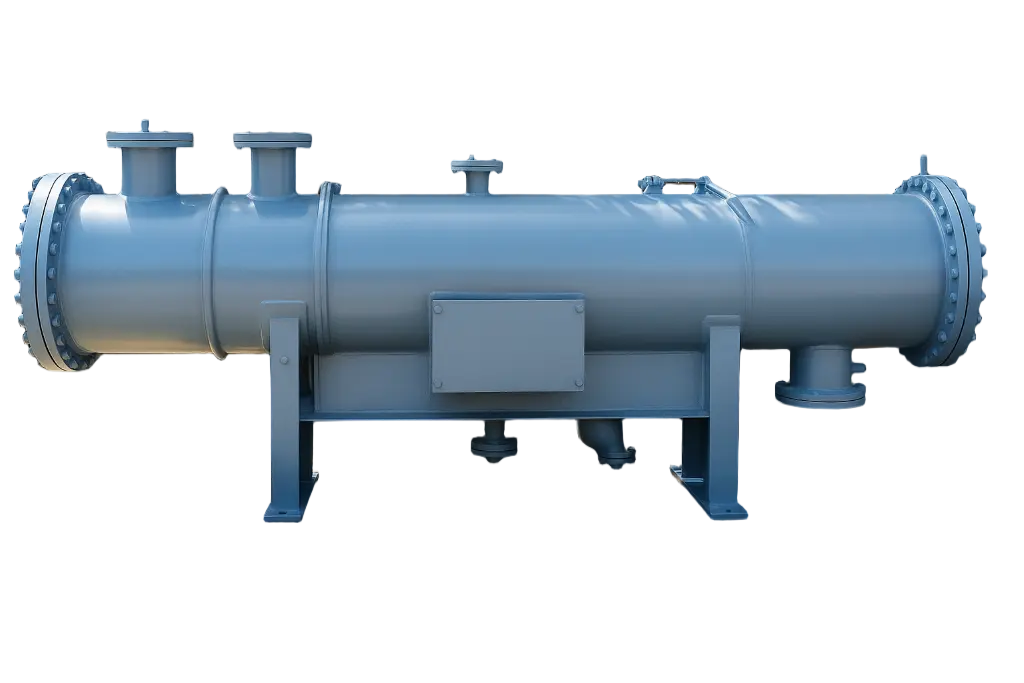
A dump condenser is a specialized, pressure-retaining heat exchanger that absorbs and condenses excess, bypassed, or emergency-discharged steam or hot vapor during transient plant events like turbine trips or startups.
Working Principle
- Transient Disposal: Unlike steady-state main condensers, a dump condenser remains on standby and instantly engages to absorb high-energy thermal loads when steam is diverted from its normal process path.
- Heat Transfer Zones: The incoming vapor goes through desuperheating, condensation (releasing large amounts of latent heat at a nearly constant temperature), and optional subcooling of the resulting condensate.
- Indirect vs. Direct Contact: Depending on the design, cooling happens either indirectly across metallic tube walls or via direct mixing of steam and cooling water.
Types
- Shell-and-Tube Dump Condensers: Steam flows over or through a bundle of metallic tubes (such as stainless steel, titanium, or copper-nickel) while cooling water circulates on the opposite side.
- Air-Cooled Dump Condensers: Uses ambient air and finned tubes to reject heat directly to the atmosphere without needing cooling water.
- Direct-Contact / Jet Condensers: Steam and cooling water mix directly for rapid condensation, used where condensate purity is not strictly required.
- A-Type and V-Type Configurations: High-capacity (A-Type) or compact auxiliary (V-Type) modular structural designs.
Design Features
- Dump Tubes & Diffusion: Strategic inlet or exhaust dump tubes (such as 90° or 360° patterns with precision-drilled holes) diffuse steam to reduce turbulence and prevent pipework stress.
- Thermal Expansion: Built with robust mechanical sizing, oversized lower condensate collection sections, and automated steam inlet/condensate control valves to handle sudden temperature spikes.
- Codes and Standards: Engineered according to HEI, ASME, TEMA, and Seismic codes, utilizing corrosion-resistant materials.
Applications
- Power Generation: Managing steam during turbine trips, emergency shutdowns, load rejections, and boiler warmups/startups.
- Industrial & Process Plants: Cogeneration systems, chemical and petrochemical plants, refineries, and pulp and paper mills where sudden vapor releases must be managed safely instead of venting to the atmosphere.
- Marine Systems: Managing residual steam flows when main propulsion turbines disengage or shift loads.
What is a dump condenser?
A dump condenser is a heat exchanger that receives steam from the turbine bypass system and condenses it. It can be a standalone unit or a dedicated section built into the main condenser.
Its job is to handle
high-energy, intermittent steam flows. These flows arise when the boiler or heat recovery steam generator (HRSG) produces more steam than the turbine can accept.
Why steam power plants need one
Boilers cannot start and stop instantly, and turbines have strict steam-condition requirements. A dump condenser bridges that gap in several situations:
- Start-up: Steam is bypassed until temperature and pressure match turbine requirements. This also shortens start-up time and limits thermal stress on the turbine.
- Turbine trip or load rejection: Steam generation continues for a while after the turbine stops. The bypass prevents safety valves from lifting and avoids sudden pressure spikes.
- Part-load operation: Excess steam is absorbed without cutting boiler output.
- Process-steam upsets: In cogeneration plants, steam is dumped when the process consumer trips.
- Water and energy conservation: Boiler-quality water is expensive to treat. Condensing it saves water, chemicals, and the heat already invested in it, and it avoids noisy atmospheric venting.
How a dump condenser works
- Pressure reduction: High-pressure steam passes through turbine bypass valves.
- : Water is injected to bring the steam temperature close to saturation.
- Distribution: The steam enters the condenser through a sparger or diffuser that spreads it evenly and reduces velocity and noise.
- Condensation: Steam gives up its latent heat to cooling water flowing through tubes (or to sprayed water in direct-contact designs).
- Collection: Condensate gathers in the hotwell.
- Return: Condensate pumps send it back to the feedwater cycle.
- Air removal: Vacuum pumps or ejectors remove non-condensable gases when the unit runs under vacuum.
Key components
| Component |
Function |
| Shell |
Pressure-containing vessel, built for thermal and pressure transients |
| Tube Bundle |
Transfers heat from steam to cooling water |
| Steam Distribution System |
Spargers or diffusers that control steam velocity and noise |
| Impingement Plates |
Protect tubes from high-velocity steam and droplets |
| Hotwell |
Collects condensate and provides level control |
| Desuperheater |
Cools incoming steam by water injection |
| Bypass Valves |
Reduce pressure and control steam flow, usually fast-acting |
| Air Removal System |
Removes non-condensable gases |
| Expansion Provisions |
Absorb differential thermal growth |
| Instrumentation |
Monitors pressure, temperature, level, and vibration |
Types of dump condensers
- Shell-and-tube (surface) type: Steam condenses on the shell side while cooling water flows through the tubes. This is the most common design because the condensate stays clean and can be reused as boiler feedwater.
- Direct-contact (spray) type: Steam mixes directly with sprayed cooling water. These units are compact and handle very large transients well, but the condensate mixes with the cooling medium and usually needs treatment or separate handling.
- Air-cooled type: Finned tubes are cooled by fans. This suits locations where cooling water is scarce, though the units are larger and condensing temperatures are higher.
- Integrated bypass section: A dedicated zone within the main condenser neck receives bypass steam. This is common in large utility turbines and saves space and cost.
Dump condenser vs. main condenser
| Feature |
Main Condenser |
Dump Condenser |
| Purpose |
Condenses turbine exhaust |
Condenses bypassed or excess steam |
| Steam Source |
Low-pressure turbine exhaust |
Boiler or HRSG steam via bypass valves |
| Duty |
Continuous |
Intermittent or transient |
| Steam Condition |
Low pressure, partly wet |
High energy, desuperheated |
| Main Design Challenge |
Efficiency and vacuum |
Thermal shock, velocity, noise |
Design considerations
- Capacity: Units may be sized for full boiler flow or a partial percentage, depending on plant philosophy. Combined-cycle plants often use partial bypass capacity.
- Thermal shock: Sudden steam admission can cause tube vibration, differential expansion, and fatigue.
- Velocity and erosion: Distribution devices and impingement protection are essential.
- Noise control: Bypass steam generates high noise levels, so diffusers and sound attenuation are often needed.
- Water hammer: Proper drainage, level control, and steam-line warming prevent condensation-induced shock.
- Pressure rating: The shell must handle both full vacuum and positive pressure during upsets.
- Material selection: Tube material (stainless steel, titanium, cupronickel, admiralty brass) depends on cooling water quality.
- Condensate quality: Surface types must protect feedwater purity.
Codes and standards
- ASME Section VIII, Division 1 or 2: Pressure vessel design
- HEI Standards for Steam Surface Condensers: Design and testing guidance
- TEMA: Tubular heat exchanger construction
- ASME PTC 12.2: Performance testing of steam surface condensers
- PED / EN 13445: European pressure equipment requirements
- Indian Boiler Regulations (IBR): Steam-related pressure parts in India
Always confirm the standards required by the local jurisdiction and project specification.
Common problems and solutions
| Problem |
Typical Cause |
Remedy |
| Tube Leaks |
Erosion, vibration, corrosion |
Eddy current testing, plugging or retubing, better impingement protection |
| Tube Erosion at Inlet |
Poor steam distribution |
Improve sparger design, add shields |
| Thermal Fatigue |
Frequent cycling |
Controlled warming, flexible supports |
| Fouling |
Poor cooling water quality |
Cleaning, filtration, chemical treatment |
| Air In-Leakage |
Flange or seal leaks |
Leak testing, joint repair |
| Hotwell Level Swings |
Control or pump issues |
Tune level control, check pump NPSH |
| Passing Bypass Valves |
Seat wear |
Valve overhaul, leak monitoring |
Maintenance and inspection
- Eddy current testing of tubes
- Visual inspection of spargers, baffles, and impingement plates
- Water-side cleaning
- Helium or vacuum decay leak testing
- Calibration of control valves, level controllers, and desuperheaters
- Testing of relief devices
- Review of vibration and temperature data after major trips
Applications
- Coal, gas, and biomass power plants
- Combined-cycle power plants with HRSGs
- Nuclear power plants
- Concentrated solar power plants
- Cogeneration and waste-heat recovery systems
- Refineries and chemical plants
- Paper mills and sugar mills with backpressure turbines
- Marine steam systems
Benefits
- Protects boilers and turbines from pressure and temperature excursions
- Enables faster, smoother start-ups
- Recovers high-quality condensate
- Reduces water, chemical, and heat losses
- Lowers noise and avoids steam venting
- Improves plant reliability and operating flexibility
FAQs
What is a dump condenser used for?
It condenses excess steam that bypasses the turbine during start-up, trips, low load, or process upsets, so the steam and water are recovered.
Is a dump condenser the same as a turbine bypass condenser?
Yes. The terms are used interchangeably, though “dump condenser” is more common in industrial and cogeneration settings.
How is it different from a main condenser?
The main condenser handles continuous turbine exhaust at low pressure. A dump condenser handles intermittent, high-energy bypass steam and is designed for thermal shock and high velocities.
Can a dump condenser be part of the main condenser?
Yes. Many large plants include a dedicated bypass section in the main condenser neck.
What standards apply?
Common references include ASME Section VIII, HEI, TEMA, and ASME PTC 12.2, plus local regulations such as IBR or PED.
What are the most common failure points?
Tube erosion near the steam inlet, thermal fatigue, air in-leakage, and passing bypass valves.
Conclusion
A dump condenser is a protective and economic asset in any steam system with a turbine bypass. By absorbing steam the turbine cannot use and recovering the condensate, it keeps the plant safe, efficient, and flexible. Correct sizing, steam distribution, material selection, and maintenance are what make it reliable.
