What is an coil heat exchanger?
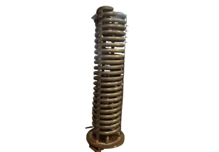
A coil heat exchanger is a device that transfers thermal energy between two fluids (such as water, oil, refrigerant, or air) without letting them mix. It uses a coiled tube structure—often helical, spiral, or fin-and-tube—packed inside a shell, tank, or air stream to maximize surface area and create high-efficiency fluid turbulence in a compact footprint
The key points are:
- The two fluids are separated by the tube wall and do not mix.
- Heat flows from the hotter fluid to the colder fluid through the wall.
- The coil shape provides a long tube length in a compact space.
- The second fluid may be a liquid in a tank, a fluid in a shell, or air blowing over the coil.
A familiar example is the cooling coil inside an air conditioner or air handling unit. Cold refrigerant or chilled water flows through the coil while warm air is blown across it. The air gives up its heat and leaves cooler.
3. A Short History and Why Coils Are Still Popular
Coiled tubes have been used for heat transfer for well over a century. Early examples include the worm coil in a distillery condenser, where vapor condensed inside a spiral tube sitting in a tub of cold water. The same basic idea scaled into steam heating coils, refrigeration evaporators, and boiler economizers.
Coils remain popular for three reasons:
- Simplicity: one tube bent into shape is easy and cheap to make.
- Adaptability: the same concept works for a 1 kW lab unit and a multi-megawatt industrial coil.
- Compatibility: coils fit inside existing tanks, ducts, and shells, so they are easy to retrofit.
4. How a Coil Heat Exchanger Works
The working principle follows one natural law:
heat always moves from a hotter body to a colder one. In a coil heat exchanger it happens in four steps:
- The hot fluid enters the coil: This might be hot water, steam, thermal oil, or compressed refrigerant gas.
- Heat moves to the inside wall of the tube The flowing fluid hands heat to the tube surface by convection.
- Heat conducts through the tube wall: Metals like copper, stainless steel, and aluminum conduct heat well, so this step is fast.
- The cold fluid absorbs the heat from the outside wall: Liquid in a tank or air passing over the coil warms up by convection.
- The hot fluid leaves cooler. The cold fluid leaves warmer. The two never touch.
A simple example: water heating in a tank
Steam flows through a coil submerged in a water tank. The steam condenses inside the tube and releases a large amount of heat through the tube wall. The tank water warms up, and the condensed steam (condensate) leaves the coil at the outlet.
A simple example: air cooling
Chilled water at about 7 °C flows through a finned coil in an air handling unit. A fan blows warm air across the fins. The air cools, and moisture in it can condense on the coil, which also dehumidifies the air.
5. The Science Behind It: Heat Transfer Basics
Understanding the physics helps explain design choices.
Three resistances in series
Heat must pass through three barriers:
- The inside film of fluid next to the tube wall
- The tube wall itself
- The outside film of fluid or air next to the outer surface
Fouling deposits (scale, dirt, biofilm) add extra resistance on either surface. The overall performance is the combined effect of all of these.
Main equations
Heat duty (sensible heat):
Q = ṁ × cp × ΔT
Heat duty (phase change, such as steam condensing):
Q = ṁ × h_fg
Heat transfer rate:
Q = U × A × ΔT_lm
Where:
- Q = heat transfer rate (W or kW)
- ṁ = mass flow rate (kg/s)
- cp = specific heat (kJ/kg·K)
- U = overall heat transfer coefficient (W/m²·K)
- A = heat transfer surface area (m²)
- ΔT_lm = log mean temperature difference (K)
- h_fg = latent heat of vaporization (kJ/kg)
Log mean temperature difference:
ΔT_lm = (ΔT₁ − ΔT₂) / ln(ΔT₁ / ΔT₂)
What this means in practice
To transfer more heat, a designer can:
- Increase the area (A) with a longer coil, more turns, or fins
- Increase the temperature difference (ΔT) with hotter heating fluid or colder cooling fluid
- Increase the coefficient (U) with higher velocity, better turbulence, cleaner surfaces, or a higher-conductivity material
Important dimensionless numbers
- Reynolds number (Re): shows whether flow is laminar or turbulent
- Prandtl number (Pr): compares momentum and thermal diffusion in the fluid
- Nusselt number (Nu): the ratio of convective to conductive heat transfer
- Dean number (De): describes flow in curved tubes, combining Reynolds number and the tube-to-coil diameter ratio
6. Why Coiled Tubes Perform Better Than Straight Tubes
When fluid flows around a curve, centrifugal force pushes the faster-moving fluid in the middle of the tube toward the outer wall. The fluid then returns along the sides toward the inner wall. This creates a pair of counter-rotating swirls called Dean vortices, also known as secondary flow.
The benefits are:
- Thinner boundary layer at the wall, so heat transfers more easily
- Higher heat transfer coefficient than a straight tube at the same flow rate
- Better mixing, so temperature is more even across the tube
- Laminar flow stays stable longer, which helps with viscous fluids
- Some resistance to fouling, since the swirling flow sweeps the wall
The trade-off is a
somewhat higher pressure drop, and tighter coils give more enhancement and more pressure loss. A good design balances the two.
7. Main Parts and Components
| Component |
Function |
| Coil Tube |
Carries the fluid and forms the heat transfer surface. |
| Fins |
Thin plates on the tube exterior that increase surface area for air-side heat transfer. |
| Header/Manifold |
Distributes fluid into the coil circuits and gathers it at the outlet. |
| Return Bends |
U-shaped fittings that connect tube runs in serpentine coils. |
| Distributor (DX Coils) |
Splits refrigerant evenly into parallel circuits. |
| Shell, Tank, or Casing |
Holds the coil and the second fluid or air stream. |
| Baffles and Supports |
Hold the coil in position and prevent vibration. |
| Inlet and Outlet Connections |
Flanged, threaded, or welded connections to piping. |
| Vent and Drain Points |
Remove trapped air and allow full draining. |
| Drain Pan |
Collects condensate on cooling coils. |
| Eliminators |
Stop water droplets from being carried into the airstream at high velocity. |
8. Types of Coil Heat Exchangers
8.1 By shape and construction
Helical coil heat exchanger
The tube is wound like a spring. It is compact, handles thermal expansion well, and gives good heat transfer. Common in process heating and cooling, storage tanks, and chemical vessels.
Spiral coil
The tube is wound flat in a single plane. It has low height and is used where vertical space is limited.
Serpentine coil
A tube with repeated U-bends in a zigzag pattern, typical of HVAC finned coils.
Shell and coil heat exchanger
A coil enclosed in a closed shell. It handles higher pressures and compact liquid-to-liquid or steam-to-liquid duties.
Tube-in-tube coil
One tube is coiled inside another. The two fluids run in opposite directions, giving true counter-flow and efficient exchange in a small unit.
Immersion (tank) coil
A coil placed directly inside a tank or bath to heat or cool the contents. Common for fuel oil, chemicals, brewing, and hot water storage.
Jacketed vessel with internal coil
A reactor or tank with both an outer jacket and an internal coil, giving extra surface for fast heating and cooling.
8.2 By function
Cooling coil (chilled water)
Chilled water flows inside the tubes and cools and dehumidifies the air. Used in air handling units, data centers, hospitals, and commercial buildings.
DX (direct expansion) evaporator coil
Refrigerant evaporates inside the tube and absorbs heat from the air. Found in split ACs, packaged units, and heat pumps.
Condenser coil
Hot refrigerant gas condenses inside the tube and rejects heat to air or water.
Hot water heating coil
Hot water flows through the tubes and warms the air passing over them.
Steam heating coil
Steam condenses inside the tube and gives up its latent heat. Used in industrial ventilation, make-up air heating, and dryers.
Steam distributing coil
A steam coil with an inner distribution tube that spreads steam evenly and helps prevent freezing in cold climates.
Reheat coil
Raises the air temperature after cooling, used to control humidity in labs, cleanrooms, and pharmaceutical areas.
Preheat coil
Warms very cold fresh air before it reaches the main coils, protecting them from freezing.
Heat recovery (run-around) coil
Two coils linked by a glycol loop capture heat from exhaust air and transfer it to incoming fresh air.
Heat pump coil
Works as an evaporator in one mode and a condenser in the other.
Economizer coil
Recovers heat from boiler flue gas to preheat feedwater.
8.3 By tube surface
- Plain (bare) tube coil: best for liquids and dirty or fouling fluids
- Finned tube coil: best for air and gas, where fins offset poor heat transfer
- Enhanced tube coil: grooved, corrugated, or dimpled tubes for higher heat transfer.
- Microchannel coil: flat aluminum tubes with louvered fins, light and compact, widely used in condensers.
9. Flow Arrangements
| Arrangement |
Description |
Result |
| Counter-flow |
Fluids move in opposite directions. |
Highest effectiveness, closest temperature approach. |
| Parallel flow |
Fluids move in the same direction. |
Lower effectiveness, but lower wall temperature extremes. |
| Cross-flow |
Fluids move at right angles, typical of air coils. |
Good performance, common in HVAC. |
| Multi-pass |
Fluid passes through the coil several times. |
Higher velocity and better heat transfer. |
For cooling coils, connecting water to enter at the air-leaving side and exit at the air-entering side creates a counter-flow effect and improves capacity.
10. Materials of Construction
Choosing the right material is critical for life and performance.
| Material |
Strengths |
Limitations |
Typical Use |
| Copper |
Very high conductivity, easy to bend and braze. |
Not suited to some corrosive fluids. |
HVAC, refrigeration, domestic water. |
| Stainless Steel 304/304L |
Corrosion resistant, durable. |
Lower conductivity than copper. |
Food, beverage, general process. |
| Stainless Steel 316/316L |
Better chloride and chemical resistance. |
Higher cost. |
Pharma, chemical, coastal. |
| Duplex and Super Duplex Steel |
High strength, resists chloride stress cracking. |
Costly, harder to fabricate. |
Offshore, severe chemical service. |
| Carbon Steel |
Strong and economical. |
Corrodes without treatment. |
Steam, thermal oil, non-corrosive fluids. |
| Titanium |
Excellent seawater and chemical resistance. |
Expensive. |
Marine, desalination, aggressive chemicals. |
| Cupronickel (90/10, 70/30) |
Resists seawater and biofouling. |
Cost. |
Marine and shipboard systems. |
| Aluminum |
Light, good conductivity, low cost. |
Weaker, prone to galvanic corrosion with copper. |
Fins, microchannel coils, automotive. |
| Hastelloy, Inconel, Monel |
Withstand severe corrosion and high temperature. |
Very expensive. |
Demanding chemical and high-temperature duties. |
| Glass, Graphite, PTFE-lined |
Resist highly corrosive acids. |
Brittle or limited pressure. |
Special chemical service. |
Fin materials and coatings
- Aluminum fins are standard for cost and weight.
- Copper fins last longer in corrosive air.
- Epoxy, polyurethane, or hydrophilic coatings protect against salt, chemicals, and moisture, and improve condensate drainage.
Selection factors
Consider fluid corrosiveness, temperature and pressure, thermal conductivity, galvanic compatibility between metals, hygiene requirements, local water quality, air quality, expected service life, and budget.
11. Manufacturing Process
- Material selection and inspection: tubes and fins are checked for quality and certification.
- Tube cutting and bending: tubes are bent on mandrels into coils, helixes, or hairpins without kinking or flattening.
- Fin stamping (for finned coils): thin sheets are stamped with collars for the tubes.
- Assembly: tubes are inserted through the fin pack or placed into the shell.
- Tube expansion: tubes are mechanically expanded to make firm contact with the fins.
- Joining: return bends, headers, and connections are brazed or welded.
- Cleaning and drying: the internal surfaces are cleaned and dried.
- Pressure and leak testing: hydrostatic, air-under-water, or nitrogen testing confirms the coil is leak-free.
- Coating and finishing (optional): protective coatings, pickling, passivation, or electropolishing.
- Final inspection and packaging: dimensions, connections, and documentation are verified.
12. Design Considerations and Sizing
Basic design steps
- Define the process: fluids, flow rates, inlet and outlet temperatures.
- Calculate heat duty (Q).
- Choose the flow arrangement and compute ΔT_lm.
- Estimate the overall U value.
- Calculate required area: A = Q / (U × ΔT_lm).
- Select tube diameter and material.
- Calculate tube length: L = A / (π × d_o).
- Select coil diameter, pitch, and number of turns.
- Recalculate film coefficients and refine U.
- Check pressure drops on both sides.
- Add a design margin of about 10 to 25 percent for fouling and uncertainty.
- Check mechanical design: pressure rating, thermal expansion, supports, vibration.
Key design factors
- Heat duty: set by flow rate and temperature change
- Fluid velocity:: high enough for turbulence and fouling resistance, low enough to avoid erosion and excess pressure drop
- Tube diameter and wall thickness: affect pressure rating, heat transfer, and pressure drop.
- Coil geometry: coil diameter, pitch, and number of turns
- Pressure drop: longer, tighter coils increase pumping power
- Fouling allowance: extra area or cleaning access for dirty fluids
- Thermal expansion: the coil must have room to move
- Vibration: supports and spacers prevent tube damage
- Codes: compliance with ASME, PED, or local pressure equipment codes
Typical overall heat transfer coefficients (indicative)
| Service |
U (W/m²·K) |
| Steam to Water |
1000–3500 |
| Water to Water |
800–1500 |
| Steam Coil in Agitated Tank |
400–1000 |
| Steam to Light Oil |
300–900 |
| Water to Viscous Oil |
60–350 |
| Water to Air (Finned, Outer-Area Basis) |
20–60 |
Values vary with velocity, fouling, and geometry. Always confirm with detailed calculation.
Air-side design factors for finned coils
- Face velocity: about 1.5 to 3 m/s for cooling coils to avoid water carryover
- Number of rows: more rows give more capacity and more air resistance
- Fins per inch: higher density increases surface but collects dirt faster
- Circuiting: affects water velocity and pressure drop
- Air pressure drop: typically 50 to 250 Pa
14. Applications by Industry
HVAC and refrigeration
- Chilled water and DX cooling coils in air handling units and fan coil units
- Hot water and steam heating coils
- Condensers and evaporators in chillers, split ACs, VRF systems, and heat pumps
- Cold storage rooms, blast freezers, and supermarket display cases
- Data center CRAH units and rear-door heat exchangers
Chemical and petrochemical
- Reactor temperature control with internal coils
- Condensing solvent vapors
- Heating viscous products, resins, and heavy oils
- Cooling process streams
Food and beverage
- Pasteurization and sterilization
- Chilling milk, juices, syrups, and beer
- Cooking and cooling vessels
- Brewery wort chillers and distillery condensers
Pharmaceutical and biotech
- Temperature control in sterile reactors and fermenters
- Water-for-injection cooling
- Hygienic stainless steel designs with polished surfaces
Power generation
- Feedwater heating
- Boiler economizers using flue gas heat
- Waste heat recovery
- Lube oil and generator cooling
Oil and gas
- Heating fuel oil, bitumen, and crude storage tanks
- Gas cooling and condensate recovery
- Offshore process cooling
Marine and offshore
- Engine jacket water cooling
- Seawater heat exchangers in cupronickel or titanium
- Shipboard air conditioning
Textile, paper, and plastics
- Dyeing machine heating
- Dryer air heating
- Hot oil and cooling water loops for extruders and molds
Metal finishing and plating
- Heating or cooling plating and pickling baths using corrosion-resistant coils
Renewable energy
- Solar water heater storage tanks with internal coils
- Geothermal ground loops
- Heat pump water heaters
Domestic and commercial
- Hot water cylinders with indirect coils
- Residential heat pumps and ACs
- Swimming pool heaters
15. Advantages of Coil Heat Exchangers
- Compact and space-saving design
- High heat transfer thanks to secondary flow in curved tubes
- Handles thermal expansion without separate expansion joints
- Simple, low-cost construction with few moving parts
- Fewer leak points, since the coil is often one continuous tube
- Flexible in application: liquids, gases, steam, and refrigerants
- Easy to retrofit into existing tanks, vessels, and ducts
- Fully customizable in material, size, tube diameter, and fin type
- Handles phase change as evaporator, condenser, or steam heater
- Wide operating range of temperature and pressure
- Low maintenance when kept clean
16. Limitations of Coil Heat Exchangers
- Internal cleaning is difficult, especially in tightly wound coils
- Not ideal for heavily fouling fluids unless cleaning access is designed in
- Higher pressure drop in long, narrow coils
- Lower efficiency than plate exchangers for some clean liquid-to-liquid duties
- Harder to inspect and repair internally
- Possible uneven flow in multi-circuit coils if headers are poorly designed
- Limited surface area per unit volume compared with very compact plate designs
- Air-side fouling reduces capacity quickly in dusty environments
17. Coil Heat Exchanger vs Other Heat Exchangers
| Feature |
Coil |
Shell and Tube |
Plate (Gasketed) |
Brazed Plate |
| Compactness |
Good |
Fair |
Excellent |
Excellent |
| Heat Transfer Efficiency |
Good |
Good |
Very high |
Very high |
| Pressure Capability |
Good |
Excellent |
Moderate |
Good |
| Temperature Capability |
High |
Very high |
Limited by gaskets |
High |
| Cleaning |
Moderate to difficult |
Easier |
Easy |
Not possible mechanically |
| Fouling Tolerance |
Moderate |
Good |
Lower |
Low |
| Thermal Expansion Handling |
Very good |
Needs design allowance |
Moderate |
Moderate |
| Gas or Air Service |
Excellent (finned) |
Fair |
Poor |
Poor |
| Typical Cost |
Low to medium |
Medium to high |
Medium |
Low to medium |
| Best For |
Tanks, HVAC, compact duties, air coils |
Large, high-pressure, heavy-duty applications |
Clean liquids, high efficiency |
Compact clean-fluid duties, refrigeration |
When to choose a coil: immersion heating or cooling in tanks, air heating or cooling, refrigeration, compact retrofit, or services needing flexibility for expansion.
When to consider alternatives: heavily fouling liquids, very large duties, or applications needing frequent mechanical cleaning.
18. How to Choose the Right Coil Heat Exchanger
Collect and confirm the following before you request a quotation:
- Fluids: identity, concentration, and whether they are corrosive, fouling, scaling, or viscous
- Heat duty: required capacity in kW, kcal/h, BTU/h, or tons of refrigeration (TR)
- Flow rates and temperatures: inlet and outlet for both fluids
- Operating and design pressure: and test pressure requirements
- Operating and design temperature
- Allowable pressure drop on each side
- Space limits: dimensions, orientation, and connection positions
- Material requirements: based on fluids, environment, and hygiene needs
- Fin type and spacing for air coils, based on dust and cleaning plans
- Coating needs for coastal, chemical, or humid environments
- Connection types and sizes
- Standards and certification: ASME, PED/CE, AHRI, Eurovent, ISO 9001, and so on
- Maintenance access: cleaning, inspection, and replacement planning
- Budget and lifecycle cost: not only the purchase price
- Delivery time and supplier support
19. Installation Best Practices
- Use counter-flow piping where possible for the best performance.
- Fit vents at the highest points and drains at the lowest points of water coils.
- Install isolation valves, strainers, and thermometer and pressure points for service and monitoring.
- Support the coil so piping weight is not carried by the connections.
- Allow service clearance for cleaning and coil removal.
- On cooling coils, slope the drain pan and fit a properly sized trap to remove condensate.
- On steam coils, use steam traps, vacuum breakers, and proper condensate drainage.
- Use dielectric fittings where dissimilar metals meet to avoid galvanic corrosion.
- Provide freeze protection: glycol, preheat coils, freeze stats, or drainable design.
- Insulate cold piping and casings to prevent sweating.
- Flush the system and clean the piping before connecting the coil to remove debris.
- Check for leaks with a pressure test before commissioning.
20. Maintenance and Cleaning
Routine schedule
| Task |
Suggested Frequency |
| Visual inspection of fins, tubes, casing, and connections |
Monthly to quarterly |
| Clean air-side fins |
Every 3 to 6 months, or as dust levels demand |
| Clean drain pan and check the trap |
Quarterly |
| Check strainers and filters |
Quarterly |
| Replace upstream air filters |
By schedule or pressure drop |
| Straighten bent fins |
As needed |
| Flush and treat water circuit |
Annually |
| Descale internal surfaces |
When pressure drop rises or performance drops |
| Refrigerant leak check |
Annually |
| Review temperature and pressure logs |
Monthly |
Cleaning methods
- Air side: soft brush, vacuum, low-pressure compressed air blown against airflow, low-pressure water spray, or a coil-safe cleaner
- Water side: chemical descaling, circulation flushing, or mechanical cleaning where the coil design allows
- Steam coils: check and replace failed traps, clear condensate lines
- Tank coils: remove external deposits during tank cleaning and inspect for pitting
Do’s and don’ts
- Do isolate, depressurize, and lock out the equipment before cleaning.
- Do use cleaners that are compatible with the fin and tube materials.
- Don’t use high-pressure jets that bend fins.
- Don’t use harsh acids on aluminum fins without proper guidance.
- Don’t let refrigerant work be handled by uncertified staff.
21. Troubleshooting Guide
| Problem |
Possible Causes |
Suggested Checks and Fixes |
| Reduced Heating or Cooling |
Dirty fins, scaling, trapped air, low flow, low airflow |
Clean surfaces, vent air, check pump or fan, check valve position. |
| High Air-Side Pressure Drop |
Dirty or blocked fins, bent fins |
Clean and comb fins. |
| High Water-Side Pressure Drop |
Scaling, blockage, clogged strainer |
Clean strainer, descale, check valves. |
| Leakage |
Corrosion, erosion, vibration, thermal fatigue, freezing damage |
Locate leak, repair or replace section, review water treatment and supports. |
| Uneven Outlet Temperatures |
Blocked circuits, poor distribution, stratified airflow |
Check header and distributor, clean circuits, improve air mixing. |
| Frost or Ice on Cooling Coil |
Low airflow, low refrigerant temperature, dirty filter |
Restore airflow, check controls and refrigerant charge. |
| Water Carryover from Cooling Coil |
Face velocity too high, no eliminators, blocked drain |
Reduce airflow, add eliminators, clear drain. |
| Poor Steam Coil Performance |
Failed steam trap, air lock, waterlogging |
Check trap, vent air, fix condensate drainage. |
| Coil Freezing (Water) |
Cold air, no glycol, valve failure |
Add freeze protection, check controls. |
| Musty Odor |
Microbial growth in wet coil or drain pan |
Clean and disinfect, ensure proper drainage. |
| Noise or Vibration |
Loose supports, high velocity, water hammer |
Secure coil, check velocity, check steam system. |
22. Energy Efficiency and Sustainability
Coil heat exchangers contribute to energy savings in several ways:
- Clean coils keep fan and pump power low and maintain design capacity.
- Heat recovery coils reuse waste heat from exhaust air or flue gas instead of releasing it.
- Larger face area and more rows allow higher chilled water temperatures, which improves chiller efficiency.
- Counter-flow design achieves closer temperature approaches, which helps boilers and chillers run efficiently.
- Variable-speed pumps and fans with modulating valves reduce energy use at partial load.
- Low-GWP refrigerants such as R32, R454B, propane, and CO₂ are encouraging smaller-diameter tubes and microchannel coils.
- Corrosion-protective coatings extend equipment life and reduce replacement waste.
- Regular maintenance avoids the efficiency loss caused by fouling, which can raise energy use noticeably over time.
23. Standards and Certifications
Depending on the application and region, look for:
- AHRI 410: rating of air-cooling and air-heating coils
- ASHRAE guidelines: HVAC design and ventilation practice
- ASME Section VIII and B31.1/B31.3/B31.5: pressure vessel and piping codes
- PED and CE marking: European pressure equipment requirements
- TEMA standards: where shell-type designs are used
- ISO 9001: quality management in manufacturing
- ISO 14001: environmental management
- Eurovent certification: performance rating of coils and air-handling products
- UL/CSA listing: safety approvals where needed
- IBR (Indian Boiler Regulations) and BIS: relevant in India for boiler and pressure equipment
- 3-A or hygienic standards: for food and dairy applications
Always confirm the exact standards required by your project and local authority.
24. Cost Factors
The price of a coil heat exchanger depends on:
- Material: copper and stainless steel cost more than carbon steel; titanium and nickel alloys cost the most.
- Size and surface area: larger coils need more tube and fin material.
- Tube diameter and wall thickness: higher pressures need thicker walls.
- Fin type and density: more fins add cost.
- Coatings and special finishes: epoxy, electropolishing, and passivation add cost.
- Design pressure and codes: certified pressure equipment needs more inspection and documentation.
- Customization: special connections, orientations, or shapes.
- Testing requirements: hydrotest, helium leak test, third-party inspection.
- Order quantity: higher volumes lower the unit price.
- Lead time: urgent orders may cost more.
Tip: compare lifecycle cost, not only purchase price. A coil with the correct material and coating may cost more at first but save on replacements and downtime.
25. Buyer’s Checklist
- Fluids and their properties confirmed
- Heat duty and temperature data confirmed
- Pressure and temperature ratings defined
- Pressure drop limits stated
- Material and coating selected for the environment
- Dimensions, orientation, and connections specified
- Standards and certification requirements listed
- Cleaning and maintenance access planned
- Supplier experience, references, and test facilities checked
- Warranty, spares, and after-sales support agreed
- Delivery schedule confirmed
- Quotation compared on total lifecycle value
27. Frequently Asked Questions (FAQs)
What is a coil heat exchanger?
It is a heat exchanger that uses a coiled tube to transfer heat between two fluids without mixing them.
How does a coil heat exchanger work?
One fluid flows inside the coil and the other flows outside. Heat passes through the tube wall from the hotter fluid to the colder fluid.
Why is the tube coiled instead of straight?
Coiling fits a long tube into a small space and creates swirling flow that improves heat transfer. It also lets the tube flex as it expands and contracts.
What are the main types of coil heat exchangers?
Helical coil, spiral coil, serpentine coil, finned tube coil, steam coil, chilled water coil, DX coil, condenser coil, immersion coil, tube-in-tube coil, and shell and coil.
Where are coil heat exchangers used?
In HVAC, refrigeration, chemical plants, food and beverage, pharmaceuticals, power plants, oil and gas, marine systems, textile, and renewable energy.
What materials are used for coil heat exchangers?
Copper, stainless steel 304 and 316, carbon steel, titanium, cupronickel, aluminum, and nickel alloys, chosen to suit the fluid and environment.
Which material is best?
There is no single best. Copper suits HVAC, stainless steel suits food, pharma, and chemicals, and titanium or cupronickel suit seawater.
Why are fins added to coils?
Air has poor heat transfer. Fins greatly increase the surface in contact with air and improve performance.
What is the difference between a coil and a shell and tube heat exchanger?
A coil exchanger uses wound tubing and is compact. A shell and tube exchanger uses a bundle of straight tubes in a cylinder and suits larger, high-pressure duties.
Is a coil heat exchanger better than a plate heat exchanger?
It depends. Plate exchangers are more efficient and compact for clean liquids. Coils are better for tanks, air service, steam, and fluids where plate gaskets or narrow gaps are a problem.
What is a helical coil heat exchanger?
It is a coil heat exchanger in which the tube is wound in a spiral like a spring, usually inside a shell or tank.
What is the difference between a cooling coil and a heating coil?
A cooling coil carries a cold fluid (chilled water or refrigerant) to cool the air. A heating coil carries a hot fluid (hot water or steam) to warm the air.
How do I size a coil heat exchanger?
Calculate the heat duty from flow and temperature change, find the log mean temperature difference, estimate the U value, and compute the area with A = Q / (U × ΔT_lm). Then choose the tube size, check pressure drop, and add a margin.
How often should a coil heat exchanger be cleaned?
Air coils usually every 3 to 6 months, depending on dust. Internal surfaces when pressure drop rises or performance drops.
How do I clean a heat exchanger coil?
Switch off and isolate the system. Use a soft brush, vacuum, or a coil-safe cleaner on fins, and chemical descaling or flushing for inside surfaces. Avoid high-pressure jets that bend fins.
What causes a heat exchanger coil to leak?
Common causes are corrosion, erosion, vibration, freezing, and thermal fatigue.
Can a coil heat exchanger freeze?
Yes, water coils can freeze in cold conditions. Use glycol, preheat coils, freeze stats, or drainable designs.
How long does a coil heat exchanger last?
With suitable materials, good water treatment, and regular cleaning, many coils last 10 to 20 years or more. Life depends on corrosion, fouling, and operating conditions.
Can coil heat exchangers be customized?
Yes. Size, tube diameter, material, fin type, circuiting, and connections can be designed for specific requirements.
What is a tube-in-tube coil heat exchanger?
A design in which one tube is coiled inside another, giving counter-flow in a compact unit.
Can coil heat exchangers work with steam?
Yes. Steam coils condense steam inside the tubes to transfer a large amount of latent heat.
What fluids can flow through a coil?
Water, glycol mixtures, steam, thermal oil, refrigerants, brine, and many process liquids, as long as the material is compatible.
28. Conclusion
A coil heat exchanger is a compact, flexible, and efficient way to transfer heat between fluids. The coiled tube provides a large surface area in a small space, improves heat transfer through swirling flow, and absorbs thermal expansion without extra parts. From air conditioners, chillers, and cold storage to chemical reactors, food plants, power stations, and ships, coil heat exchangers support heating and cooling in nearly every industry.
Getting the best results depends on choosing the right type, material, size, and flow arrangement, installing it correctly, and keeping it clean. With sound design and regular maintenance, a coil heat exchanger delivers reliable performance, energy savings, and a long service life.
Call to Action
Need a custom coil heat exchanger for your plant, HVAC system, or process line? Contact us today for design support, a detailed quotation, and expert technical advice. [Add your company name, phone, email, address, and website here.
